

|
|
|
|---|---|---|
Watertank Overflow detection using the RAKwireless WisBlock modules. It implements as well a trick to wake up the device from sleep by knocking on the enclosure.
The code is based on my low power event driven WisBlock API
Here in the Philippines it is essential to have a water tank, because it is (unfortunately) still quite common that
the water supply is cut off.
After I got my tank installed, I experienced several time that the floating valve
that controls the refill of the tank got stuck and the tank was overflowing for hours before I detected it.
As
there is no outlet close to the water tank, I needed a low power, solar recharged overflow sensor that can transmit
the data over a longer distance.
RAKWireless WisBlock has all components I needed to build my
overflow sensor.
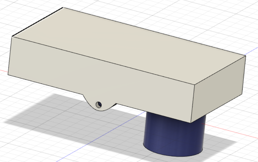
The enclosure is not IP65 but can protect the electronics from water intrusion unless the device is submerged into the water. It was designed using Fusion 360. The data files for the enclosure and the small solar panel can be found in the http://giesecke.tk/assets/3D folder.
 |
 |
 |
|---|---|---|
The sensor wakes up every 1 minute (configurable) and measures the distance between the Laser ToF sensor and the water surface. It packs the data into a data package in Cayenne LPP format and includes:
The data format is
uint8_t data_flag0 = 0x01; // 1 Channel # 1
uint8_t data_flag1 = 0x02; // 2 Analog Input
uint8_t level_1 = 0;       // 3 Water level
uint8_t level_2 = 0;       // 4 Water level
uint8_t data_flag2 = 0x02; // 5 Channel # 2
uint8_t data_flag3 = 0x02; // 6 Analog Input
uint8_t batt_1 = 0;       // 7 Battery level
uint8_t batt_2 = 0;       // 8 Battery level
uint8_t data_flag4 = 0x03; // 9 Channel # 3
uint8_t data_flag5 = 0x66; // 10 Presence sensor (Alarm)
uint8_t alarm_of = 0;       // 11 Alarm flag overflow
uint8_t data_flag6 = 0x04; // 12 Channel # 4
uint8_t data_flag7 = 0x66; // 13 Presence sensor (Alarm)
uint8_t alarm_ll = 0;       // 14 Alarm flag low level
The data is sent as a LPWAN packet over a RAK7258 gateway to a local
Chirpstack LPWAN server.
The Chirpstack LPWAN server has two integrations enabled:
Once Chirpstack has received a data packet for the Overflow sensor, it forwards the data to the two
integrations.
I used Datacake because it is a very comfortable tool to visualize the data:
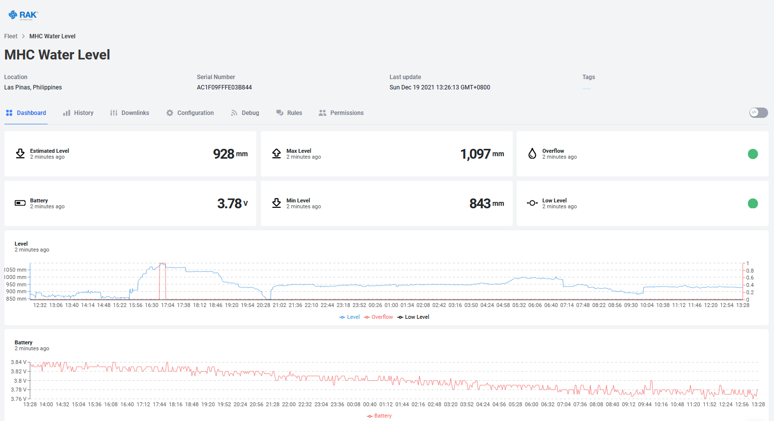
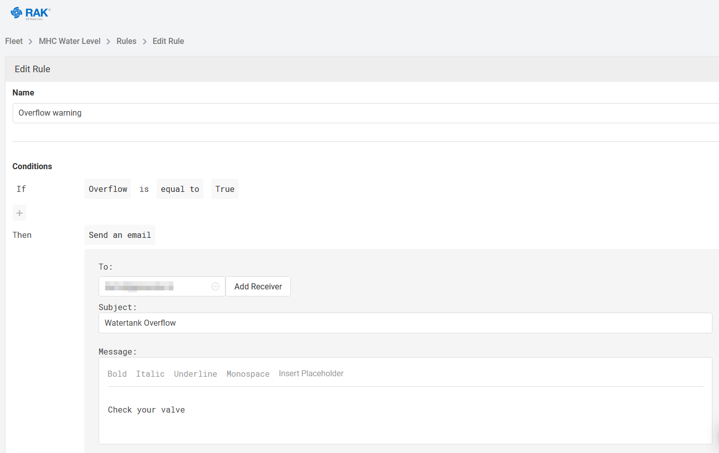
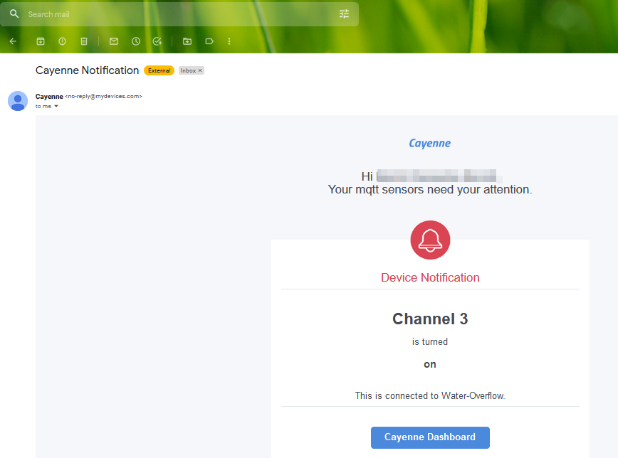
In Datacake you can setup rules that can send out on email on events. I use it to send an email if the Alarm value is true:
And I added Cayenne LPP MyDevices, because it has more features to take actions on events by using triggers.
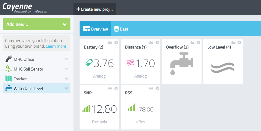
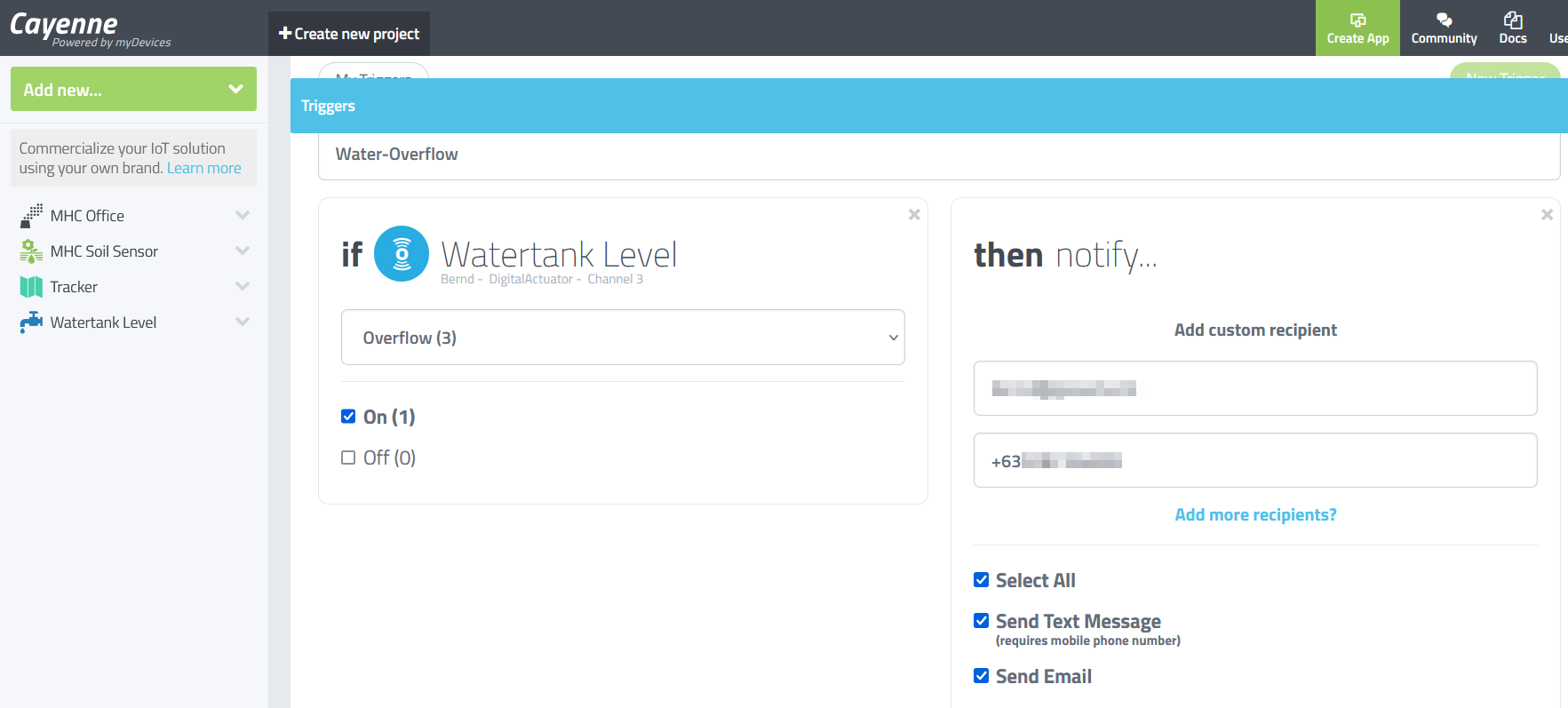
The data Alarm is connected to a Cayenne LPP MyDevices
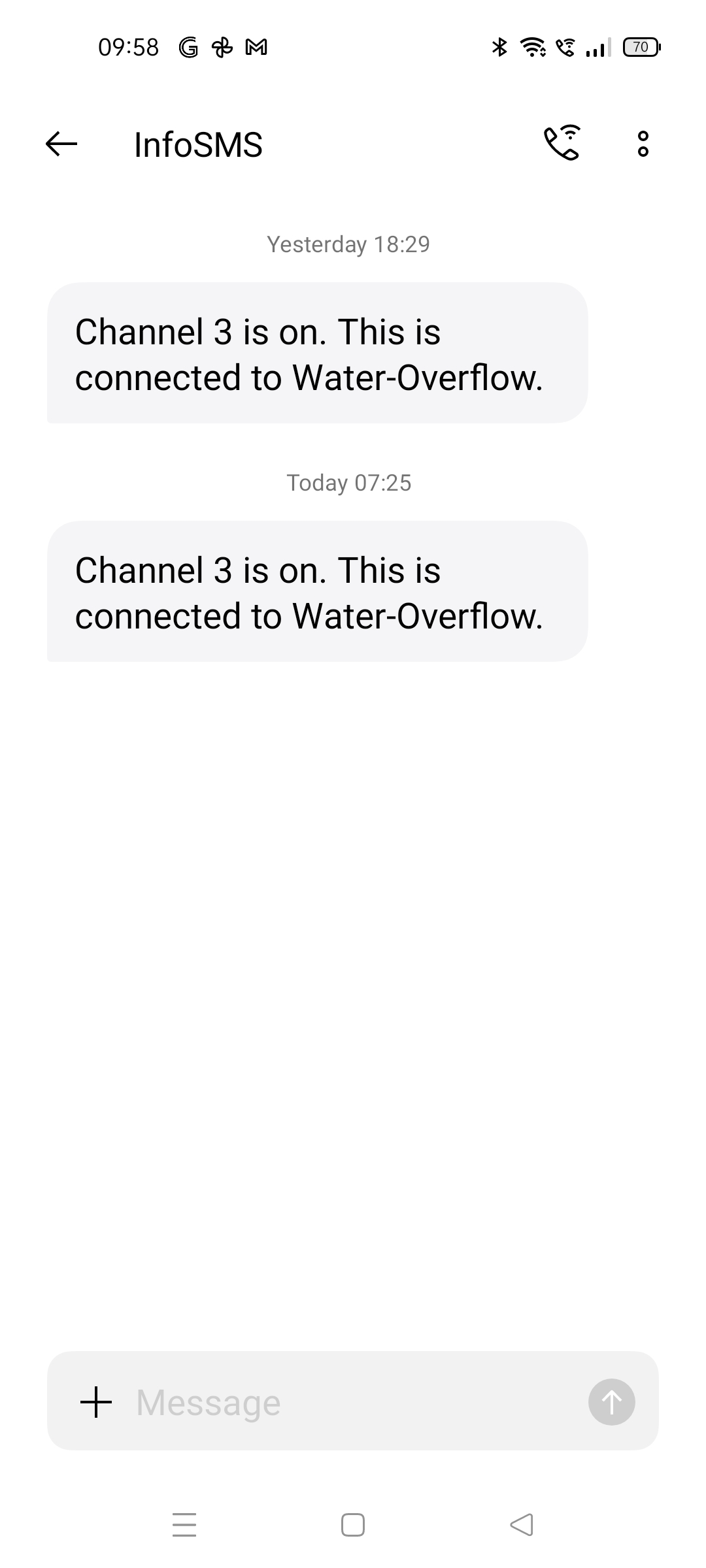
trigger that sends an email and a text message if the overflow sensor sends an alarm:
The received alarm messages:
 |
 |
|---|---|
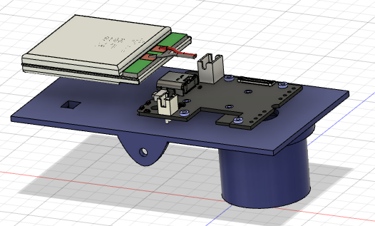
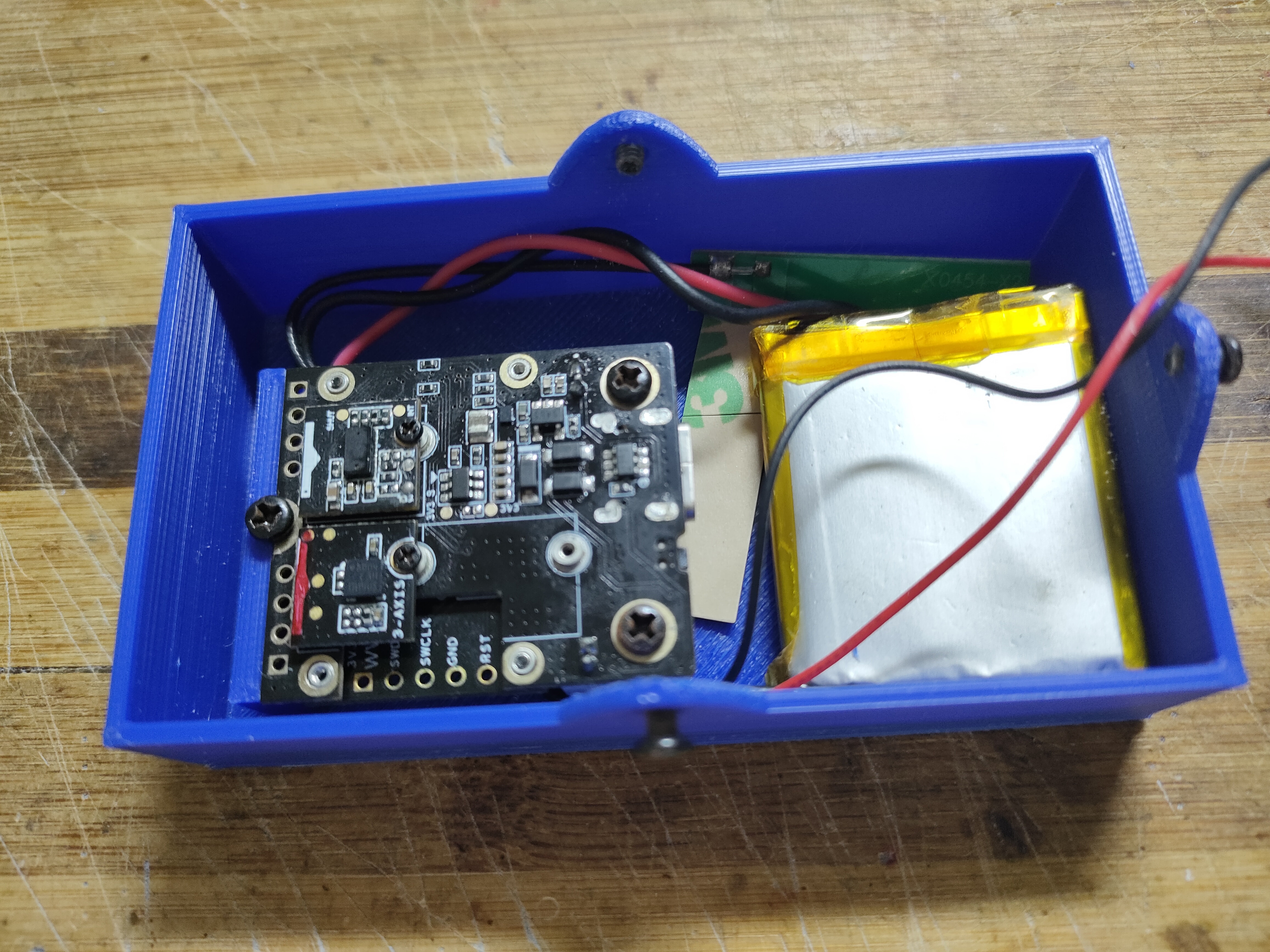
The sensor uses a small 400mAh battery, which is sufficient for this application, as the sensor is only 10 seconds
active every 1 minute.
The battery is recharged during the day by a solar panel. The panel I used is 5V output
panel, so that I can directly connect it to the WisBlock Base board.
 |
 |
 |
|---|---|---|
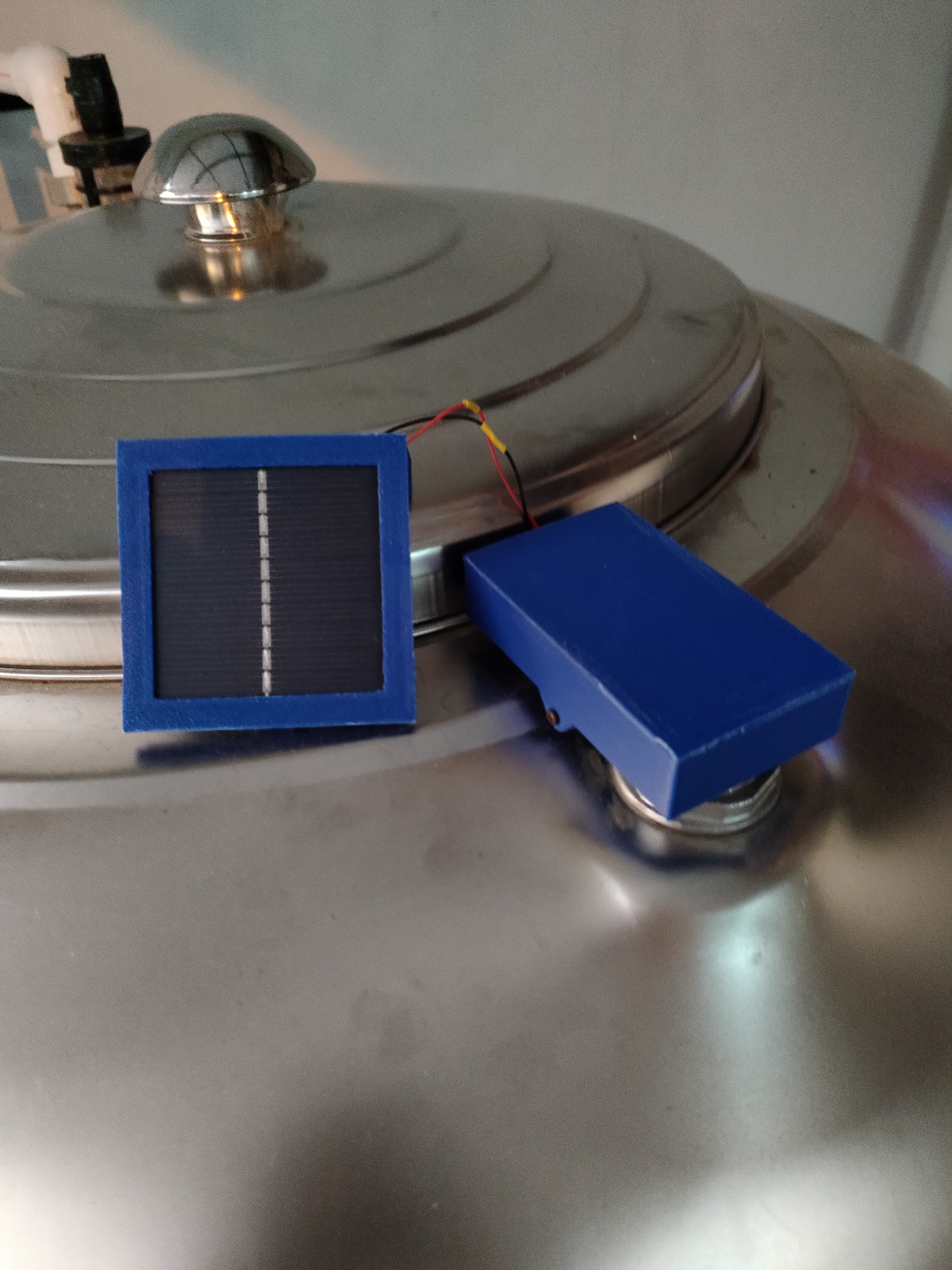
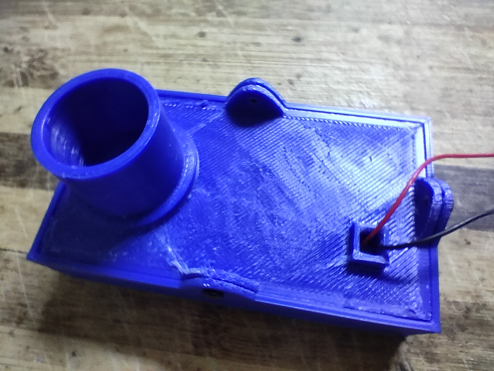
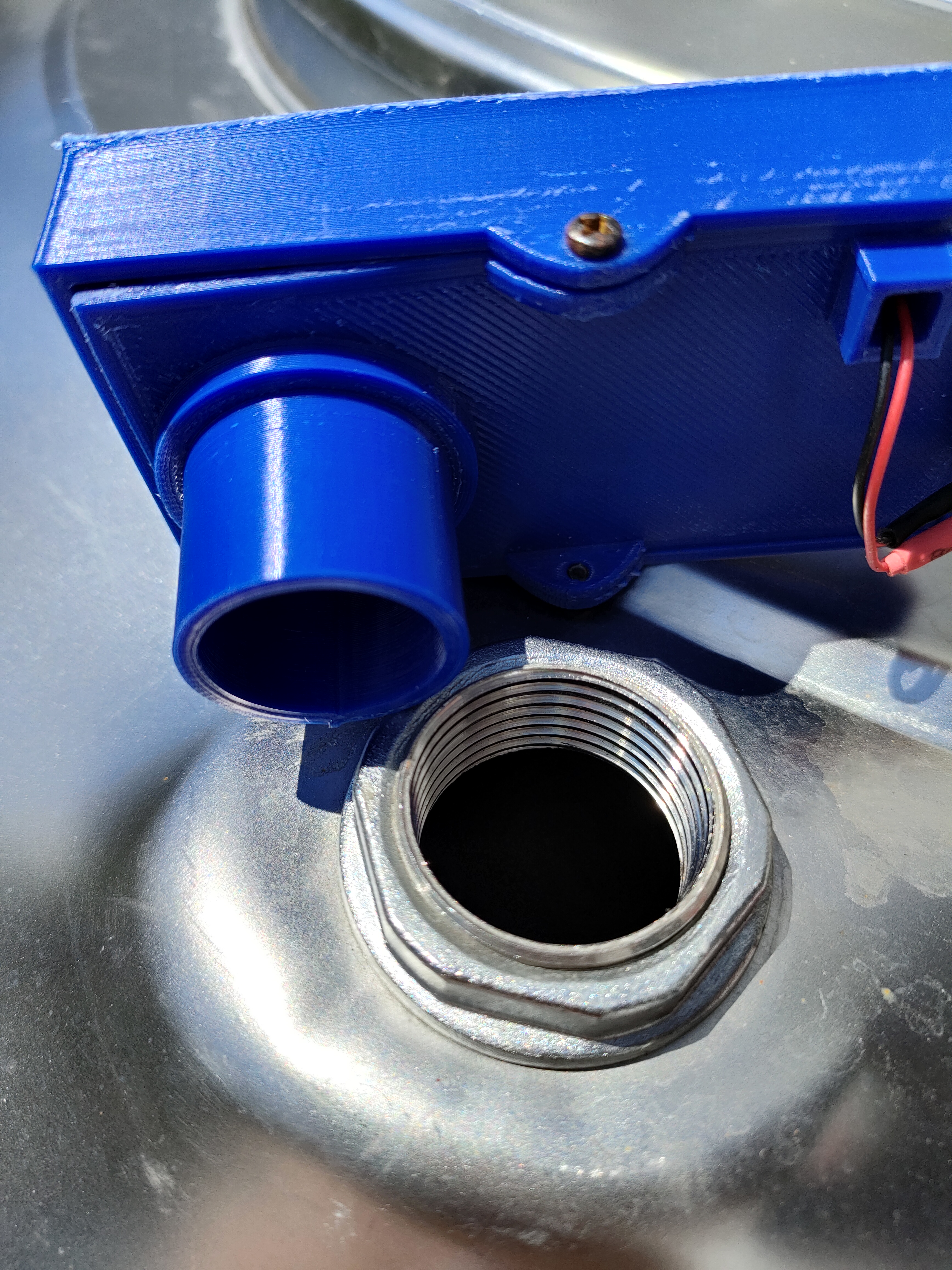
The sensor is installed in an unused refill hole of the watertank. The 3D printed enclosure has a pipe that matches the diameter of the refill opening:
 |
 |
|---|---|
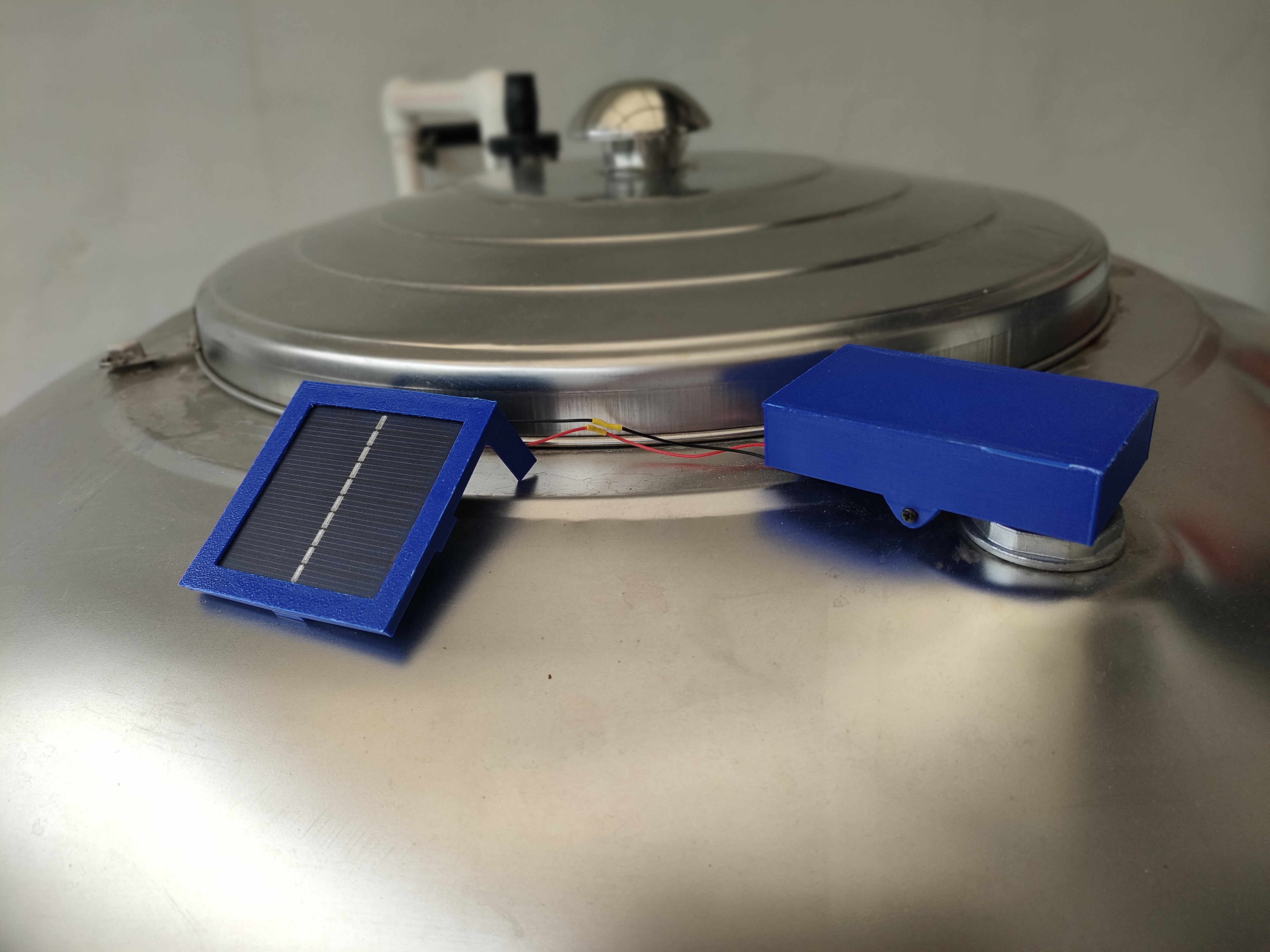
The sensor is just loose in the refill opening and the solar panel is placed on top of the water tank:
|
 |
|---|---|
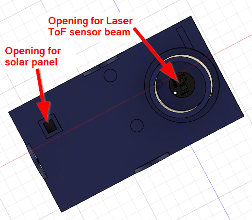
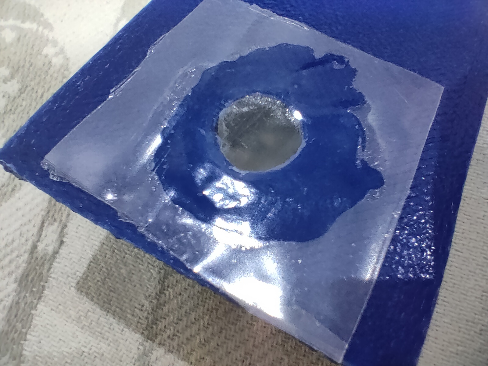
To protect the inside of the enclosure against condensing water from the tank the opening at the Laser ToF sensor is sealed with a peace of plastic glued to the enclosure:
To lower battery consumption, the device advertise its services (LPWAN setup and BLE UART) only for 30 seconds after
power up. After that the BLE advertisement is shut off.
But sometimes the BLE connection is required to change
settings, update the firmware over BLE or debug over BLE UART.
To avoid opening the device or do a power cycle to restart the BLE advertising, I added the RAK1904 accelerometer
and set it up so that it triggers an interrupt if it detects a movement in any direction. If the interrupt is
triggered, the device wakes up and enables the BLE advertising for 15 seconds, so that the WisBlock Toolbox can
connect to it.
To trigger the interrupt, a simple knock-knock on the enclosure is sufficient to be detected by the accelerometer.
The application does switch off the Laser ToF module and the MCU and LoRa transceiver go into sleep mode between measurement cycles to save power. I could measure a sleep current of 20-40uA of the whole system.
The libraries are all listed in the platformio.ini and are automatically installed when
the project is compiled.
The LoRaWAN settings can be defined in three different ways.
Using the WisBlock Toolbox you can connect to the WisBlock over BLE and setup all LoRaWAN parameters like
More details can be found in the WisBlock Toolbox
The device is advertising over BLE only the first 30 seconds after power up and then again for 15 seconds after
wakeup for measurements. The device is advertising as RAK-GNSS-xx where xx is the BLE
MAC address of the device.
Using the AT command interface the WisBlock can be setup over the USB port.
A detailed manual for the AT commands are in AT-Commands.md (external link)
Here is an example for the typical AT commands required to get the device ready (EUI's and Keys are examples):
// Setup AppEUI
AT+APPEUI=70b3d57ed00201e1
// Setup DevEUI
AT+DEVEUI=ac1f09fffe03efdc
// Setup AppKey
AT+APPKEY=2b84e0b09b68e5cb42176fe753dcee79
// Set automatic send frequency in seconds
AT+SENDFREQ=60
// Set data rate
AT+DR=3
// Set LoRaWAN region (here US915)
AT+BAND=8
// Reset node to save the new parameters
ATZ
// After reboot, start join request
AT+JOIN=1,0,8,10
The AT command format used here is NOT compatible with the RAK5205/RAK7205 AT commands.
void api_set_credentials(void);
This informs the API that hard coded LoRaWAN credentials will be used. If credentials are sent over USB or from My
nRF Toolbox, the received credentials will be ignored. It is strongly suggest NOT TO USE hard coded
credentials to avoid duplicate node definitions
If hard coded LoRaWAN credentials are used,
they must be set before this function is called. Example:
g_lorawan_settings.auto_join = false;                            // Flag if node joins automatically after reboot
g_lorawan_settings.otaa_enabled = true;                            // Flag for OTAA or ABP
memcpy(g_lorawan_settings.node_device_eui, node_device_eui, 8); // OTAA Device EUI MSB
memcpy(g_lorawan_settings.node_app_eui, node_app_eui, 8);        // OTAA Application EUI MSB
memcpy(g_lorawan_settings.node_app_key, node_app_key, 16);        // OTAA Application Key MSB
memcpy(g_lorawan_settings.node_nws_key, node_nws_key, 16);        // ABP Network Session Key MSB
memcpy(g_lorawan_settings.node_apps_key, node_apps_key, 16);    // ABP Application Session key MSB
g_lorawan_settings.node_dev_addr = 0x26021FB4;                    // ABP Device Address MSB
g_lorawan_settings.send_repeat_time = 120000;                    // Send repeat time in milliseconds: 2 * 60 * 1000 => 2 minutes
g_lorawan_settings.adr_enabled = false;                            // Flag for ADR on or off
g_lorawan_settings.public_network = true;                        // Flag for public or private network
g_lorawan_settings.duty_cycle_enabled = false;                    // Flag to enable duty cycle (validity depends on Region)
g_lorawan_settings.join_trials = 5;                                // Number of join retries
g_lorawan_settings.tx_power = 0;                                // TX power 0 .. 15 (validity depends on Region)
g_lorawan_settings.data_rate = 3;                                // Data rate 0 .. 15 (validity depends on Region)
g_lorawan_settings.lora_class = 0;                                // LoRaWAN class 0: A, 2: C, 1: B is not supported
g_lorawan_settings.subband_channels = 1;                        // Subband channel selection 1 .. 9
g_lorawan_settings.app_port = 2;                                // Data port to send data
g_lorawan_settings.confirmed_msg_enabled = LMH_UNCONFIRMED_MSG; // Flag to enable confirmed messages
g_lorawan_settings.resetRequest = true;                            // Command from BLE to reset device
g_lorawan_settings.lora_region = LORAMAC_REGION_AS923_3;        // LoRa region
// Inform API about hard coded LoRaWAN settings
api_set_credentials();
REMARK!
Hard coded credentials must be set in void setup_app(void)!
The packet data is in Cayenne LPP format. Every time the sensor data are collected, they are stored in a structure that is build in a format that most LPWAN servers and Integrations can easily parse. See Dataflow for details of the packet data format.
The compiled files are located in the ./Generated folder. Each successful compiled version
is named asWisBlock_WL_Vx.y.z_YYYY.MM.dd.hh.mm.ss
x.y.z is the version number.
The version number is setup in the ./platformio.ini file.
YYYY.MM.dd.hh.mm.ss is
the timestamp of the compilation.
The generated .zip file can be used as well to update the device over BLE using either
My nRF52 Toolbox repo or Nordic nRF Toolbox or
nRF Connect
Debug output can be controlled by defines in the
platformio.ini
_LIB_DEBUG_ controls debug output of the
SX126x-Arduino LoRaWAN library
_MY_DEBUG_ controls debug output of the application itself
_CFG_DEBUG_ controls the debug output of the nRF52 BSP. It is recommended to keep it off
[env:wiscore_rak4631]
platform = nordicnrf52
board = wiscore_rak4631
framework = arduino
build_flags =
    ; -DCFG_DEBUG=2
    -DSW_VERSION_1=1 ; major version increase on API change / not backwards compatible
    -DSW_VERSION_2=0 ; minor version increase on API change / backward compatible
    -DSW_VERSION_3=0 ; patch version increase on bugfix, no affect on API
    -DLIB_DEBUG=0    ; 0 Disable LoRaWAN debug output
    -DMY_DEBUG=0     ; 0 Disable application debug output
    -DNO_BLE_LED=1   ; 1 Disable blue LED as BLE notificator
lib_deps =
    beegee-tokyo/SX126x-Arduino
    sparkfun/SparkFun LIS3DH Arduino Library
    beegee-tokyo/WisBlock-API
extra_scripts = pre:rename.py